Editing trees (2D)
In Neurolucida 360, neuronal processes are drawn according to the principle of directionality, with the starting point being considered the beginning, and the last point considered the ending. The default branch ordering method is centrifugal. When calculating branch orders, the program applies directionality.
In order to change directionality, one of the endings must be designated as the new ending (Origin Ending).
- Click Trace>Edit>Select objects.
- Click the tree of interest to select it.
- Hover the cursor over an ending.
- Right-click the ending and select Change Ending Type.
- Select Origin Ending.
- The trees are then re-ordered, and the existing beginning is changed to a Generated Ending.
A beginning cannot be changed directly to an ending because, if there are multiple branches, Neurolucida 360 won't know which one to designate as the beginning.
If you notice that you missed a node while tracing, you can easily add it later.
- Click Trace>Edit>Select objects.
- Click a tree to select it.
- Right-click and select Insert Node into Selected Tree.
- Click to place a new node.
- The new node is represented by a filled circle.
- It is inserted at the Z value of the point immediately preceding the node.
- To trace the branch that emanates from this node, hover the mouse over the node until N appears, indicating that the mouse is in the correct position to select the node.
- Right-click and select Add Branch.
Neurolucida 360 switches from editing to tracing mode with the process already selected.
- The next left click inserts the next point in the new branch, so adjust the focus and process diameter appropriately before clicking.
Node with only one process (i.e., no branches)
- Right-click it and select Eliminate Node. The process now appears as one continuous process.
- Click Trace>Edit>Select objects.
- Click to select the tree that you want to remove from the node.
- Right-click the point of this process nearest to the node and select Remove Branch from Tree.
- Remove all other trees in a similar manner until the node only has one process extending distally from it.
- Right-click the node and select Eliminate Node.
To join the removed branches together as a separate tree, splice them.
- Right-click over the ending and select Add to Ending.
- The program switches from Editing mode to Tracing mode and displays a dialog box.
 .
.- Yes - The program automatically sets the Z stage position to the Z value of the ending.
- No - You will manually adjust the Z value with Move>Z axis>Set stage Z.
- To continue tracing in the next section, see .
- Click Trace>Edit>Select objects.
- Click to select the tree.
- On the branch to be detached, Place the cursor over the point immediately after the branching node.
- Right-click and select Detach branch from tree. The segment between the node and the point on the branch is deleted.
- Click Trace>Edit>Select objects and click a branch to select it.
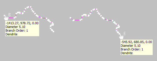
- Place the cursor over the end of the branch, right-click and select Splice. A line extends from the end to the cursor.
- Move the cursor over the end of the branch you want to join to. A circle appears at the end.
- Click to splice the two branches. You are prompted to "adjust the Z values of the spliced branch to match those of the selected neuron."
Click No to avoid introducing distortion into the Z position of the newly joined branch.
- Click Trace>Edit>Select objects.
- Click the tree to select it.
- Right-click and select change tree to color.
- If you're not satisfied, right-click and select Undo last color change.
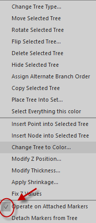
If markers are attached to the tree, changing tree color will also change marker color. To keep the original marker color, uncheck Operate on attached markers in the right-click menu. When you're done with the color change, make sure to re-check the option so that markers remain attached. 
For example, you used the axon type for a tree but you realized that it is a dendrite.
- Click Trace>Edit>Select Objects.
- Click a tree to select it.
- Right-click and select Change Tree type.
To see the options, select the tree then right-click slightly away from the tree.
Enables you to start a new tree (instead of a branch) from a node. Useful to trace axon-carrying dendrites where axon emanates from a dendrite.
Same as Trace>Tools>Correct Z shrinkage command.
Most commonly used when flipping sections that were mounted upside down (Flipping a single section with a completed tracing).
Choose a different color for the traced process.
Change to axon, dendrite or apical dendrite.
Copy to the clipboard.
Delete the traced process.
Corrects large deviations in the Z values. The Z discrepancy that is corrected by Fix Z Values is the same as the Z value that triggers a Z Position Out of Range warning during tracing.
When Fix Z Values is selected, any move in Z position larger than this specified value is automatically corrected. The Z values shown in the Orthogonal View window do not change until you exit the editing mode.
See Nodes and Branches above.
Use to increase the precision of the tracing.
You can also use the slider in the Edit Tool panel.
To display the thickness, go to File>Preferences>Display Preferences>View and check Display Thickness.
- Set Z Values: Specify the absolute Z value for the tree. If multiple objects are selected, the Z value is applied to all the selected objects.
- Shift Z Values: Moves the tree(s) up (positive value) or down (negative value) a given number of microns.
Once this option is selected, you can drag the tree to another location.
Rotates the tree or group of trees around the center point indicated by a green target icon.
- Drag the green target icon to change the location of the rotation center.
Selects all the objects the same color as the selected tree.
Also see Editing trees (3D), Editing Individual Points, Editing Spines, Using Markers
