Camera-stage alignment
Purpose
Once you've added and tightened the objectives to be calibrated, the next step is to align the camera and stage. Precise alignment is important for
Materials needed
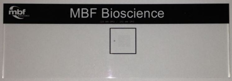
- MBF calibration-grid slide (or a graticule slide with known scaling)
- [Possible]: Allen wrenches for aligning camera and stage.
Before you start
- Turn on the microscope system, including the computer.
- Start Neurolucida software.
- If applicable, add and/or remove objectives to and from the microscope and create software lenses for new objectives.
- Tighten installed objective(s) by hand.
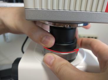
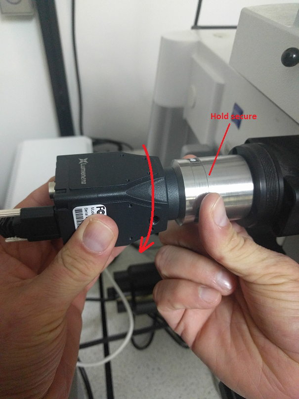
- If you have moved or changed your camera, make sure that it is securely attached to the c-mount that attaches it to the microscope. Hold your camera with one hand and the c-mount with the other, and gently rotate the camera clockwise. For camera-stage alignment, you will rotate the camera and camera mount together as a single unit.
Procedure
-
Set up for the alignment:
-
Place the calibration-grid slide on the stage.
-
Engage a mid-power lens on the microscope (e.g., 10x or 20x) and select the same lens in Neurolucida software from the drop-down menu on the Quick Access toolbar at the top of the main window.
(If the software lens has not been created, you'll need to do that first; see Creating a lens for instructions.)
-
Place a reference point on the screen (anywhere is fine).
-
Bring the grid appropriate for the objective into focus:
- 10x and lower-power objectives: Use the 250 µm (large) grid
- 20x and higher-power objectives: Use the 25 µm (small) grid
-
-
Verify that the camera is oriented in the proper direction: What appears through the eyepiece should be identical in orientation to what appears on the screen.
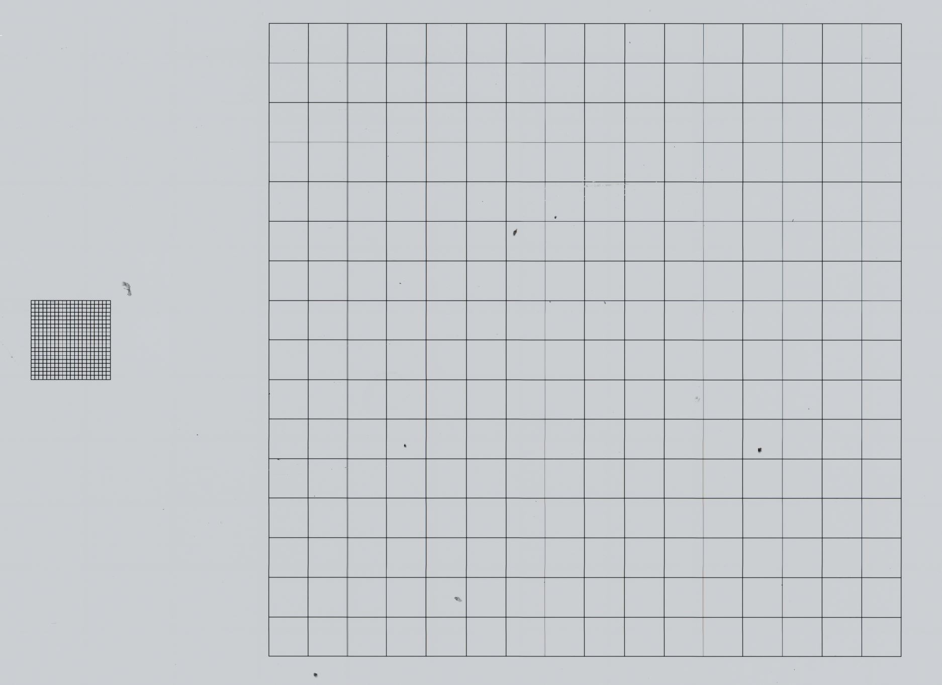
Example with the MBF Bioscience calibration grid slide: If the small grid is to the left of the large grid when looking through the eyepiece, then it should appear the same way on the computer screen. If it appears backwards, you need to rotate the camera 180°.
-
To adjust the camera orientation, loosen the set screw on the camera mount and rotate the camera. Tighten the set screw when finished.
-
-
 Click the Show Grid button from File > Calibration; a white grid appears on the screen
The grid overlay should be the same size as the grid on the calibration slide; if it isn't:
-
Double check that the software lens selected matches the objective in place on the microscope.
-
If the physical and software lenses match, check grid preferences:
 Click the Grid preferences button from File > Calibration (or open grid preferences by going to File > Preferences > Display >Tracing window section). If necessary, adjust the X and Y Grid Spacing to match the grid that you're using (either 250 x 250 µm or 25 x 25 µm). Note that if the grid boxes are still not the same size, it is an indication that the lens is not calibrated correctly.
-
-
Conduct a preliminary camera-stage alignment by aligning the software and calibration-slide grids:
-
 Click Joy Free on the Move ribbon to control stage movements with the joystick and to enable moving the stage independently of the software grid.
 -
Move the stage to align the grids as closely as possible.
-
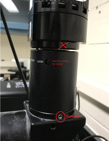
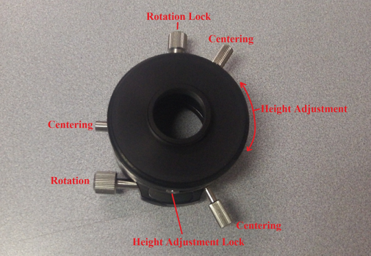
If needed, rotate the camera and c-mount together so that the grids can be aligned:
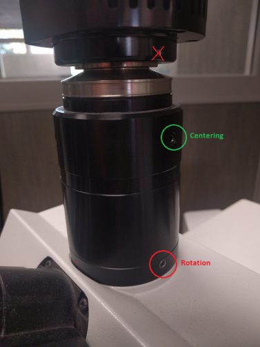
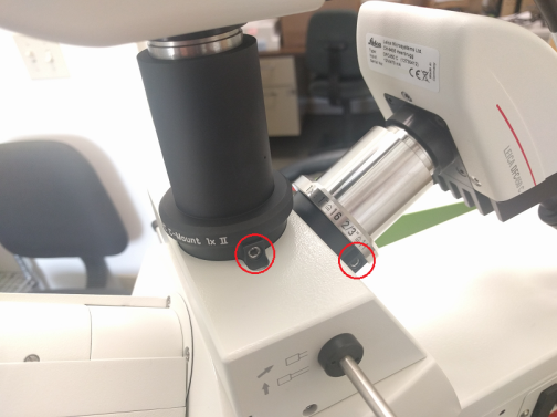
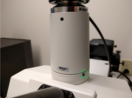
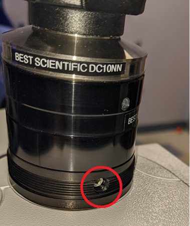
- Loosen the set screw (sometimes located at the bottom of the c-mount). Camera rotation on most c‑mounts can be adjusted by using a 2.5 or 3 mm hex wrench to loosen/tighten a set screw (see common c‑mounts here).
- Slowly turn the camera slightly in either direction until the two grids line up on the screen. Don't make large adjustments or the camera may become oriented backwards.
- Tighten the set screw to set it into place; this provides a starting point for camera-stage alignment. Aligning the grids is NOT sufficient for proper calibration.
-
At this point, the camera and stage are sufficiently aligned to Auto-calibrate lenses.
Continue with this procedure to align and calibrate manually.
-
-
-
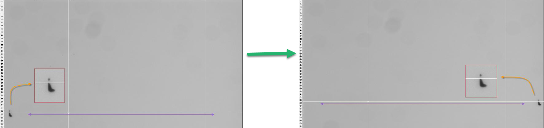
Still in Joy-Free mode, find a dust or debris particle on the grid slide that is easy to identify (e.g., particle with a defining mark or protrusion). This is called the "unique point" in the following instructions.
-
Move the stage to align this unique point to the top of a white grid line on one side of the screen.
-
Move the stage in either X or Y so that the unique point moves all the way across the screen. Evaluate its position relative to the reference line:
-
With a perfectly aligned camera, the unique point will remain aligned with the reference line. The camera-stage alignment is complete.
-
If the unique point has moved more than a few pixels relative to the reference line:
-
Adjust the camera alignment with the stage as described in step 4 to bring the unique point back to its original position relative to the reference line.
Note that the camera may move slightly as you tighten the adjustment screw. You will want to take this into account as you rotate the camera. Because of this, it's a good idea to re-check the alignment one more time after tightening.
-
Move the stage back towards its original position, observing the position of the unique point relative to the reference line—readjust the camera rotation if needed.
-
Once the position of the unique point remains aligned with its reference line as you move the stage as far as possible in both directions, the camera is aligned with the stage.
-
Tighten the set-screw on the c-mount securely into place and check the alignment one more time after tightening the screw.
-
-
-
-
Once the camera-stage alignment is complete, click the Show Grid button again to turn off the grid.
Examples of common c-mounts