3D environment overview
|
|
View your image or image stack, plus your reconstruction data in three dimensions, as a partial projection, or as cross sections. Reconstruct and edit To open the 3D Environment, click the 360 button in the Trace, Image, or Workspace ribbon. |

See also Neurolucida 360 interface overview, 3D window button bar.
Tools in the 3D environment
Trace/detect and edit structures:
Segment and annotate your image data:
- Split large and/or complex images into Subvolumes to facilitate analysis.
- Select a color channel for display onscreen and to associate with structures as you model them using the Channel panel.
- Define Contours (regions of interest) and Edit Contours in the 3D environment
- Place Markers or Edit Markers right in the 3D environment
Present your data to others:

|
Create video clips using movie mode. |

|
Export your 3D model with a click |

|
Use the Set Scene Rotation tool to specify the perspective (image rotation in X, Y, and Z) when creating figures or movies to share your work. |

|
Take a snapshot of what is displayed in the 3D visualization window |
Moving and displaying images and data
Navigating with your mouse
- Drag to rotate (3D view only).
- Scroll the mouse wheel to zoom.
- Hold down the SHIFT key and drag to pan (3D only).
- Drag to pan (projection views only).
Additional image navigation options
|
|
Use the Set Scene Rotation tool to indicate the degrees of rotation in X, Y, and Z to rotate the image. The effect is equivalent to dragging the image with your mouse, but with more precision. |

|
Use the 2D rotation tool to spin a stack and change its orientation: click the button and drag to rotate clockwise or counterclockwise. |

|
Use the move-pivot-point tool to change the rotation axis: click the button, then click the new rotation point in the image. When you drag the image, it will rotate around the new point. |

|
Click to return to the original orientation of the image. |
3D and cross-section (image slice) views
 Click the Image button to access the Change Image Display controls.
-
3D Volume is the default view. You can choose to show just portion of the 3D volume by selecting partial projection and adjusting sliders in the user interface.
-
Image Slice mode is also available. Display or hide planes (XY, XZ or YZ) to facilitate your work.
Selecting color channels for display and association with modeled structures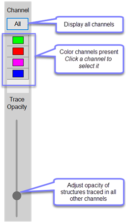
Use the Channel panel on the left side of the 3D window to select and work in specific color channels in multichannel images.
- Click any color button(s) to choose it for display.
- When a single color channel is selected, any structures traced or detected will be associated with that color channel.
- To change the color channel, click to select a different one.
- To show all color channels present in the image, click the All button. If All channels are selected, structures traced are not assigned to a channel.
- Use the Trace Opacity slider to control the visibility of structures traced in other channels. This does not affect the appearance of structures traced in the currently selected channel.