Combined point intercept probe
Purpose

|
Use the combined point intercept probe to estimate area and boundary length in thin sections. |
How it works
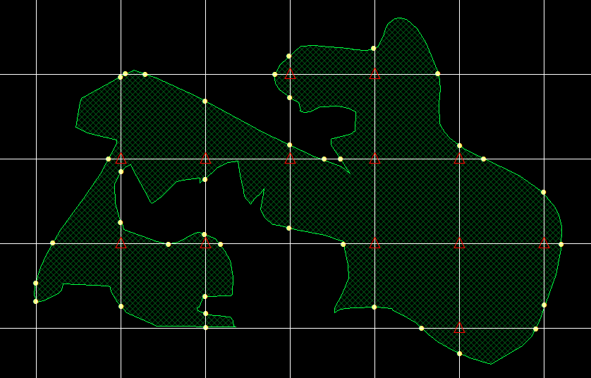
A grid of known dimensions is used to probe for both area and boundary-length.
-
To estimate the area, mark the vertices of the grid (i.e., points) that are part of the cross-section of the 3D object (red triangles in the figure).
-
To estimate the boundary-length, mark the intersections of the grid with the surface of the object (yellow circles in the figure).
Related probes
-
To estimate boundary length with vertical sections, use L-cycloid or IUR Planes.
-
To estimate boundary length with thick preferential sections, use Spaceballs or Isotropic Virtual Planes.
Procedure
-
 Click Combined Point Intercept on the Probes ribbon.
 If you haven't used the probe recently, find it in the Length drop-down menu.
 - In the Combined Point Intercept window, enter a separation value and an angle value. You will need to experiment to determine an appropriate separation to obtain a statistically significant number of intersections.
-
-
Right-click and select Mark Lines.
-
Click each point where the object's boundary line intersects with the grid to places a tick mark at the intercept.
You can change the shape and size of the tick marks in File > Preferences > Stereology Preferences > Display.
-
-
Mark each vertex (grid intersection) that falls within the region of interest.
- Right-click and select Mark Vertices.
- Click to place a tick mark at each vertex (intersection of horizontal and vertical grid lines) that falls within the region of interest. (The same marker used for the intercept is placed.)
- When you have finished marking intercepts and vertices, right-click and click Exit CPI.
-
 To view results, click Probe run list in the Stereology Results section of the Probes ribbon.
See Combined Point Intercept formulas equations.