Coordinate spaces in NeuroInfo
Purpose
Frequently asked questions about NeuroInfo include what do the coordinates of points in the data files mean? What is the coordinate space in which those points reside?
NeuroInfo operates with multiple coordinate spaces. This page describes how they are defined.
The experiment image
The optical image formed by a microscope is a continuous function. The domain of the function is spatial (2D or 3D) and the range of the function relates to light intensity. The digital image acquired by a camera attached to the microscope is a discrete sampling of this function. The digital image is represented as a structured grid of intensity values (pixels).
A digital microscopy image therefore has two coordinate systems that can be used to describe its contents. The image's pixel coordinates (let's call the axes i, j, and k) are indices into the structured grid of intensity values as stored in computer memory.
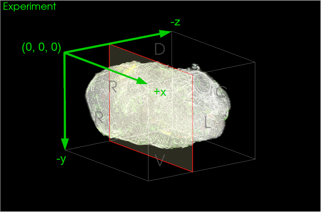
The image's physical coordinates (let's call the axes x, y, and z) relate to where in space the image was acquired. NeuroInfo, like all MBF Bioscience software, applies a stage-based physical coordinate space to images. When viewed on a computer monitor, the positive axes of this coordinate space point left-to-right of the screen (x), bottom-to-top of the screen (y), and out towards the viewer (z), respectively (Figure 1).
In NeuroInfo, the origin of the experiment image's coordinate space corresponds to the first pixel in the image at the left, upper, top corner as displayed on screen. The image's micron/pixel scaling provides the final element that fully establishes the physical coordinate space for an image: origin, spacing, and direction.
Note that this means the positive j and k pixel coordinate directions correspond to negative y and z physical coordinate directions.

|
| Figure 1. NeuroInfo stage-based coordinate space for an experiment image. |
The Allen CCF Atlas Space
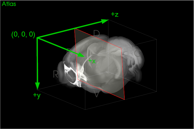
Every atlas also has a physical coordinate space and several images that are located within this space. For example, the MBF Bioscience version of the Allen Institute for Brain Science Common Coordinate Framework (CCFv3) mouse brain atlas employs a coronal-oriented adaptation of the CCFv3. The origin of this space is the first pixel in the reference image, and the physical coordinates are defined in terms of the animal's anatomy: the positive axes point right-to-left, dorsal-to-ventral, and rostral-to-caudal, respectively (Figure 2).
(Note that NeuroInfo works with other atlases, but without loss of generality, we'll use the MBF Bioscience version of the CCF in this explanation.)

|
| Figure 2. NeuroInfo physical coordinate space of the MBF Bioscience coronal adaptation of the Allen CCFv3. |
NeuroInfo registration
NeuroInfo registration finds the mapping between the physical coordinate spaces of the experiment image and the atlas. The result of registration is a geometric transform that maps points in the experimental image onto corresponding points in the atlas.

The first step in determining the transform between spaces is to align the anatomic directions of the two spaces. This is accomplished with the Anatomic Orientation tool in the calibration section of the Section and Volume registration panels that prompts users to establish the principal anatomic directions that correspond to the axes of the experiment image. The other registration tools further refine this initial transform to find the mapping between the experiment and atlas coordinate spaces.
Mapping between coordinate spaces
 The operation Map Experiment to Atlas transforms markers and contours in the experiment coordinate space into the atlas coordinate space. In the resulting _points.csv file, the "Experiment" coordinates are marker positions in the experiment's physical coordinate space and the "Atlas" coordinates are those marker positions in the atlas' physical coordinate space (Figure 3).

|
|
Figure 3. Example _points.csv file from Map Experiment to Atlas shows marker coordinates in the physical experiment and atlas spaces. |
Note that the points in the _output.xml file, however, are in the MBF Bioscience stage-based coordinate space applied to the atlas coordinate space. Specifically, the y and z axes of this coordinate space are inverted relative to the atlas' coordinate space. This is done so that the _output.xml file can be loaded into any MBF Bioscience software, and the atlas images and mapped geometries are all displayed properly.
The Allen CCFv3
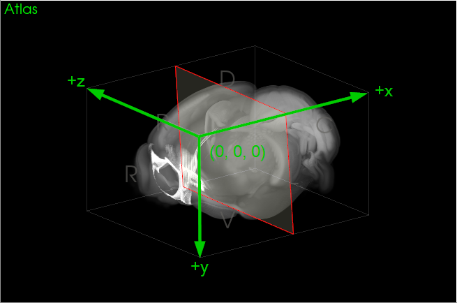
If an image is registered to the MBF Bioscience coronal adaptation of the Allen CCFv3, how do coordinates in that atlas space relate to the official sagittal-oriented Allen CCFv3?The Allen CCFv3 physical coordinate space places the origin at the first pixel of their sagittal reference image and the positive axes point rostral-to-caudal, dorsal-to-ventral, and left-to-right, respectively. To map a point from the MBF Bioscience version of the CCFv3 to the Allen CCFv3, then, requires reordering the x and z coordinates and inverting the resulting z coordinate (Figure 4).

|
| Figure 4. The sagittal-oriented Allen CCFv3 coordinate space. |