Edit Vessels Panel (3D)
See Editing vessels (3D) for detailed instructions. See also Tracing vessels in the 3D environment.
Purpose

|
Use the Edit vessels panel in the 3D Environment to change vessels that have already been modeled. |
To view more options in the panel, select vessels first (click the Select All button or click on a vessel that has been drawn).
In multi-color-channel images, if vessels are associated with a single color-channel (that is, if a color channel was selected prior to tracing or detecting the vessels), select that color channel (using the Channel panel or the Image Adjustment tool) to access all of the vessel-editing functions.
Tools and controls in the Edit vessels panel
Selection and Show/Hide Controls
-
Select All: Click to select all the traced vessels.
Alternatively you can select one or several vessels with the mouse:
-
To select a single vessel, click the vessel.
-
To select several adjacent vessels, press the CTRL key and draw a marquee (rectangle) around the vessels of interest.
-
-
Hide/Show Selection controls
-
Select a vessel and click the Hide selection button to hide it.
-
You can show the vessel if it is still selected by clicking the Show selection button
-
Click the Show all hidden button to "unhide" all vessels that are hidden.
-
Vessel-editing tools
-
 Points: Click to view the vessels displayed as a series of points (Points mode). Click again to exit Points mode.
Points mode enables Detach at a specific point, Connect and Directionality. You can also move and delete points, and adjust point thickness.
- To select a point, click it. To select multiple adjacent points, hold down Ctrl and draw a marquee (rectangle) around the points of interest.
- To move a point, drag it.
- To delete a selected point, press the Delete key.
-
 Detach: Click to enable/exit Detach mode.
 If you also click Points, you'll be able to detach with more precision.
-
Click a vessel to detach.
-
If you click on a single segment, the vessel is split in two.
- If you click the site of a bifurcation, the vessel is split in three.
-
- Exit Detach mode by clicking the Detach button again
-
-
 Connect: Click to enable/exit Connect mode.
 Vessels are displayed as a series of points in Connect mode.
-
Click and drag an end point toward the desired connection point. The end point briefly turns green and a green line appears when a connection can be made. Release the mouse button to connect the vessel segments.
-
-
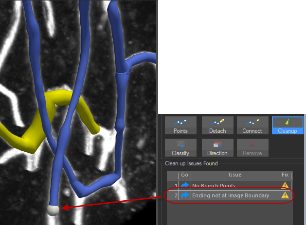
 Cleanup: After tracing complex structures using user-guided or automatic tracing, there may be vessel fragments. Cleanup identifies these issues and helps you resolve them quickly.
 Click to learn more.
Types of issues:
- No branch points: The vessel doesn't include any node or branch point: Edit manually to fix this issue.
- Vessel fragment found: The vessel has two or less points: clicking Fix will delete the vessel.
- Ending not at image boundary: The ending point is not at the image boundary: Edit manually to fix this issue.
Solutions (Fix column):
 The fragment can be deleted automatically.
 Manual editing is recommended (e.g., merging).
- To delete all the fragments marked by in the list, click the Clean All button.
- To inspect a specific issue, click on it in the list and the corresponding area in the tracing will be highlighted.

- To resolve a specific issue, click in the Fix column.
-
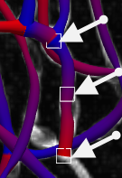
 direction: Visualize and/or modify flow direction: Click to visualize the flow direction for all traced vessels at the segment level—red indicates the origin/beginning of segment, blue indicates the distal side/end of the flow.
 When a segment is selected, you can see three squares that designate the segment's beginning, middle and end.

-
Change direction: Click to reverse the flow direction of the segment; you should see the segment recolor so that the new beginning point becomes red.
-
Direction can be changed for individual segments, but not for entire vessels.
-
Note that you can only change the direction of a segment that is connected to another segment and has one open endpoint.
-
-
Set/Clear origin toggle button: Click to define or clear the origin of selected segments that are connected to other segments and have one open end.
-
Click a segment to select it then click the Set origin button. This will update the flow direction and set the origin to the open endpoint.
-
Click Clear Origin to undo. Note that this does not revert the direction of the flow; click Change direction to revert the flow direction.
-
-
-
 Classify: Click to enable classification of vessel segments for later analysis in Vesselucida Explorer software:
If applicable, see separate instructions for SPARC users below.
-
Click to select a segment; a selected segment is indicated by three white squares (beginning, middle, and end of segment).
Use CTRL-click to select several segments.
-
Select a name from the Segment Namedrop-down menu to classify the selected segments.
To customize the names in the list, click the Color sets button, highlight a name and type a new name.
-
When you save, then open, the data file in Vesselucida Explorer, the classified structures are listed in the Networks tab of the Traced Structures panel.
SPARC users will see a slightly different interface that displays anatomic terms associated with the subject information entered when Vesselucida 360 software was launched. To classify vessel segments in SPARC mode, do the following:
-
Select the segment(s) you want to classify.
-
Find the classification for the selected segment(s) by scrolling or searching the anatomical terminology list.
To search the list, start typing into the Search Terms box.
-
Click the classification to apply it to the selected segment(s).
-
-
 Remove: Click to delete selected vessels/segments.
Alternatively, click the Delete key on your keyboard to delete selected vessels/segments.
Appearance and data controls
-
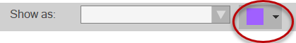
Show as: Use the drop-down menu to choose how selected vessels are displayed.
-
Color Picker: The color picker to the right of the Show as drop-down menu can be used to change the color used to represent vessels. To change the color of selected vessels, click the arrow near the colored square and choose a color from the color picker.
-
Channel: In images with more than one color channel, use the drop-down menu to associate the selected vessels with a specific color channel.
Changing a vessel color-channel does affect the data associated with the image.
-
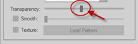
Transparency: Drag the Transparency slider to increase the transparency of selected vessels.
(You may want to hide vessels instead.)
-
Smooth: Check the box and drag the slider to smooth the appearance of selected vessels (they will appear less jagged).
This feature is for visualization purposes only (e.g., snapshots for publications); it does not affect your data.
-
Surface: Use the drop-down menu to choose a surface effect. (This feature is for visualization purposes only, e.g., snapshots for publications; it doesn't affect your data.)
 Click the ellipsis to access additional surface specific controls including gradient colors, transparency, and other context dependent settings.
-
Vessel Color: Displays vessels as the color they were originally traced as, or as the color chosen from the Color Picker.
-
Class: Displays vessels in classification colors if they have been Edit Vessels Panel (3D).
-
Diameter: Displays the diameter (µm) of the vessels as a color gradient.
-
Direction: Displays direction of vessels as they move away from their origin as a color gradient.
-
Distance to Markers: Displays distance (µm) between vessels and markers as a color gradient. Must have a marker present.
-
Distance to Puncta : Displays distance (µm) between vessels and puncta as a color gradient. Must have a punctum present.
-
Distance to Spines: Displays distance (µm) between vessels and spines as a color gradient. Must have a spine present.
-
Distance to Varicosities: Displays distance (µm) between vessels and varicosities as a color gradient. Must have a varicosity present.
-
Texture: Allows you to select an image from a browser window and apply it to the surface of selected vessels. The image must be one of the following formats: .png, .tif, .jpg, or .bmp.
-
-
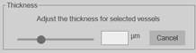
Thickness: You can change the thickness of an entire vessel or the thickness at a single point (or a group of points).
Changing the thickness of a vessel does affect the data associated with the image.
-
Click a vessel to select it or click the Points button and select the points you want to adjust. Drag the slider or type a value in µm for the thickness you want.
-