Serial Section Manager
Purpose
|
|
Use the Serial Section Manager to define the key parameters (i.e., initial section thickness, Z position, etc.) for each section. |

Adding or inserting new sections
-
 Open the Serial Section Manager by clicking its icon from the Workspace or Trace ribbon.
 -
In the Serial Section Manager window, click one of the following:
-
 New section: Add the first serial section or add a new section to the bottom of the list.
 -
A new section is added to the bottom of the list if there are existing sections in the Serial Section Manager.
-
The Serial Section Setup window is displayed if you are adding the first serial section.
-
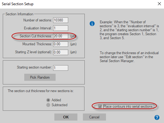
Under Section Information, enter / modify the requested information.
-
Select Added or Subtracted to indicate how new sections are handled.
When you focus down through a section, the depth value increases in the negative direction. For example, if sections are 10 µm thick, and the top of the section is at a depth of 0, the bottom of the section is at a depth of −10 µm.
-
-
Click OK to complete the setup.
-
-
-
 Insert Section: Add a section at a specific Z-location to the existing list.
The Add New Section window opens:
-
Enter/modify the requested information; the value entered as the Top of Section Depth determines the Z location of the new section.
-
Focus on the top of the section and click OK to add the new section.
-
-
Once the first section (or series of sections) has been defined, New section automatically adds a new section to the end of the section list using the parameters specified previously in Serial Section Setup.
Creating sections from contours
This is useful when you have multiple sections in one image. After outlining each section, you can create serial sections based on the contours of the sections (see Outline sections to automatically create contours).
-
In the Serial Section Manager window, click the New section button .
- In the Serial Section Setup window:
- Fill out Section Information, including section thickness.
- Check Place contours into serial sections.
 09iu
09iu
The first serial section contains the top left section (i.e., contour) in the image. Contours are used from left to right, starting with the top row. 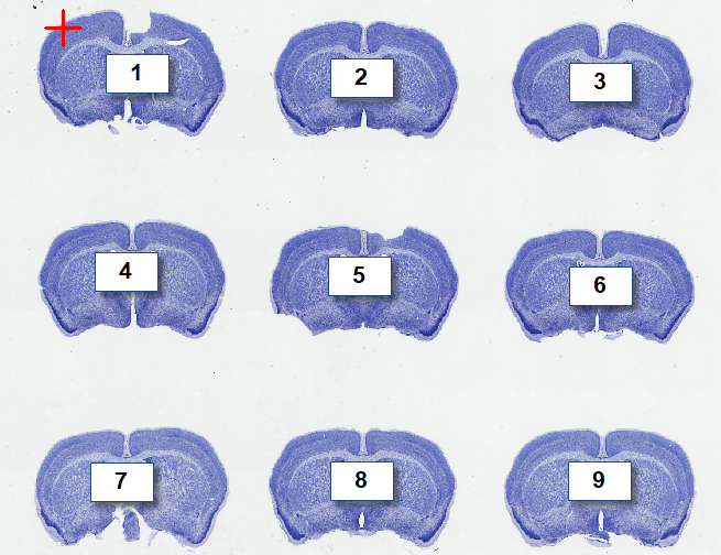
Tools and settings reference
Section Z column
-
Displays the depth value associated with each section. This is usually the Z coordinate for the top of the section.
-
Data contained within a section is not restricted to the Z range of that particular section.
-
Data points placed in a section can have any Z value, but generally the data make more sense if you restrict the Z values to those contained within the section.
Section Name column
-
Displays the name assigned to each section; either the default name, or the name you assign.
Toolbar button functions
|
|
New section |
Add a new section at the bottom of the list. |
|
|
Insert section |
Insert a section at a specific Z position relative to existing sections. |

|
Edit section |
Edit the properties of the selected section. |

|
Select by section |
Select all objects in the current section. |

|
Show current section |
Display the currently selected section only. |

|
Gray other sections |
Display objects not in the current section as gray
|

|
Show flanking sections |
Display the sections immediately above and below the current section as gray (e.g., if section 9 is active, sections 8 and 10 are displayed as gray and section 9 is shown in color).
|

|
Delete section |
Delete the currently selected section. The locations of the other sections are not changed with the deletion of a section. |

|
Delete all other sections |
Delete all sections except the currently selected section. There is no Undo function for this operation. |