Correcting for an upside down section while tracing
One of the most frustrating situations you can encounter when mapping serial sections is to realize after the fact that the section you have been mapping was mounted on the slide upside down.
To remedy this problem:
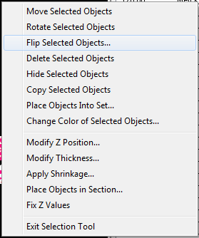
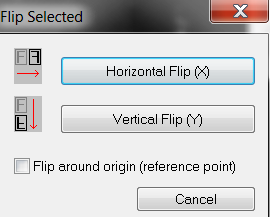
- Click Trace>Edit>Select All Objects.
- Optional: If Z positioning is critical, correct the depth values:
- Select Trace>Tools>Correct Z shrinkage. Enter "-1" as the factor
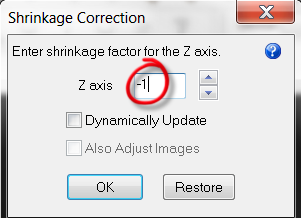 .
. - Calculate the correct delta.
- Right-click and select Modify Z Position. Select Shift Z values and enter the delta value calculated in step 4.b.
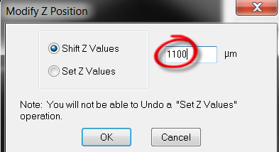
- Select Trace>Tools>Correct Z shrinkage. Enter "-1" as the factor
- Align the new section.
- Enable Show Current Section.

- Use your preferred alignment method:
- Move>Align tracing>Match points
- Trace>Edit>Select All Objects
- Select the contours.
- Right-click and select Move selected contour or Rotate selected contour.
- Enable Show Current Section.
- Define the new section using Workspace>Tracing> Serial section manager.
- Click the New Section icon to add a new section to the list.
- Double-click on the new section to open the Modify Section Information dialog box.
- Type in the nominal depth value for the bottom of this section in the Top of Section Depth field. Note that all Z coordinates within the section are recorded in the correct orientation.
See Tracing neurons in serial sections (2D)
- Flip all the section tracings side up again by following Steps A.1-A.3.
- Resume the Serial Section Reconstruction process with the next (correctly aligned) section.
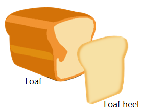
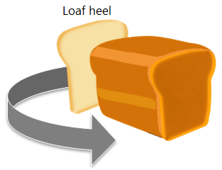
If this seems confusing, imagine a loaf of bread with a heel. You want to put the heel back on, but it is upside down (that is, the crusty side of the heel faces the loaf).
See Flipping a single section with a completed tracing if you have already completed tracing a data file and notice that one of the sections appears to be upside down.
