Batch pipeline
Purpose

|
The Batch Pipeline tool is designed to speed up your work. Use it to apply image filters in multiple image/image stack files at once, without opening them. The Batch Pipeline replaces the Batch Filter tool present in previous versions of NeuroInfo. |
Procedure Overview
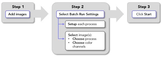
Adding images to the batch pipeline
-
 In the Main window, go to the Pipelines ribbon and click Batch Pipeline.
The Batch Pipeline window opens.
-
 Click Add images; the Image Open dialog opens.
 Select the images that you want to process; hold the shift or Ctrl key to select multiple images.
-
Click Open to add the selected images to the Batch Pipeline.
The images you opened and their file paths will be listed in the Input Image column of the Batch Pipeline window.
Note that, depending on your computer hardware, image stacks with thousands of image planes may not be compatible with processing using the batch pipeline, causing NeuroInfo to hang or freeze.
Buttons
Load images into the Batch Pipeline
 Remove all images from the Batch Pipeline
 Enable selection of multiple images so that you can set their batch processing settings
 Click to start the batch process
Table columns
Note: You can resize the table columns by dragging the vertical dividers
-
 Copy: Create a copy of the image. This is convenient for running different batch processes on a single image, e.g., to evaluate settings in preparation for a large batch processing run.
 -
 Delete: Delete the image from the Batch Pipeline.
 -
Input Image: File names and locations of images that have been added to the Batch Pipeline are displayed
-
Status: Displays "Setup Required" if you need to specify processing settings.
Displays “Ready to start” once the process settings have been selected.
Once the batch process is launched, general information about status is displayed.
-
Detail: Details of the batch-process status are displayed during processing.
-
 Open: Click it to open the processed file in the Main window.
Image Filtering
(Recommended) Identify appropriate image-filter settings for your images
Before processing a large group of images using the batch pipeline, we recommend that you identify appropriate image-filter settings first. To do this, follow the Procedure for batch image-filtering below to apply the image filter of your choice to one or a few representative images. Here are some tips for doing that:
-
Once you have added your representative image(s) to the batch Pipeline, use the
Copy button to create a few copies. -
Set up several configurations of the filter that you intend to use with different settings that you want to test.
-
Review the results and identify the settings that provided the best results.
-
Repeat and fine-tune as needed.
Procedure for batch image-filtering
-
Load images for batch processing as described above.
-
Set up/modify image filters if you have not already done so (or go to Step 3 if your image-filters are ready):
-
 In Batch Settings on the right, click the Image Filter Setup button. The Image Filter Setup window opens.
 -
 Click Add Configuration to set up a new image filter.
 To modify an existing image filter, select the saved configuration that you want to change and click Edit Configuration. Note: this will overwrite the existing configuration.
 -
Specify a name and settings:
-
Type a name for the filter, for example "Golgi default" or "Golgi 10px edge".
-
Select the Filter Type from the drop-down menu.
-
A default file-name suffix populates the Output Label field; you can change this by typing into the box.
-
Adjust the filter settings. See Image filters and settings below for specific information on settings for the available image filters.
-
-
 Click Save Changes to add the new/modified configuration to the Saved Configurations list and make it available for use in the Batch Pipeline.
 -
 Click Return to list to close the Image Filter Setup window and return to the Batch Pipeline window.
-
-
Select images and choose image-filters and color channels for batch processing:
One image at a time
-
Select an image by clicking its row in the Batch Runs table; the row will be highlighted in blue to indicate that the image is selected.
-
In the Batch Settings section on the right, select an image-filter configuration from the Image filter drop-down menu.
-
Check the boxes to choose the color channel(s) to include in the image-filtering process.
Multiple images
-
Click Select Multiple to enable selection of more than one image.
-
Select images by clicking their rows or click Select All; blue highlight indicates the images that are selected.
-
In the Batch Settings section on the right, select an image-filter configuration from the Image filter drop-down menu.
-
Check the boxes to choose the color channel(s) to include in the image-filtering process.
-
 Click Apply to finish choosing batch pipeline processing settings for the selected files.
-
-
The Status column for each image loaded into the pipeline should read "Ready to start."
You can view the settings chosen for each image by clicking on it in the Batch Runs table (blue highlight indicates the file that is selected). The chosen processing settings are displayed in Batch Settings on the right.
-
Click Start to launch the batch process.
-
The Detail column displays the current status of the process.
-
When processing is complete, the Status column will read "Completed" and you can view the results by clicking the open-file icon in the Open column.
-
Image filters and settings
Golgi: Reduces out-of-focus signal in brightfield microscopy.
The Golgi his filter cuts down the out-of-focus shadows that are the result of labeled structures in the tissue. It only works for solidly labeled objects such as those produced by Golgi staining and cannot be used for improving the appearance of very transparent or weakly-labeled structures, nor for improving the appearance of small blurry objects.
-
Compression: Use the slider to indicate your desired file-compression ratio.
-
Sensitivity: Used to control the amount of signal necessary for an object to be selected as part of the foreground structure. To capture weakly-labeled structures, you can use values greater than 100%.
-
Edge clearance: Used to mitigate edge artifact that may occur if the algorithm takes into account information from the edge of the image.
With edge clearance >0, the algorithm processes the edge, but without using contrast information within the specified number of pixels around the image.
-
Brightfield image: Leave the box checked if you're working with a brightfield microscopy image.
In vivo: Removes motion artifacts in images from live specimens.
Consecutive in vivo-acquired images in a stack may appear slightly shifted and distorted at high resolution due to blood flow in and around the field of view. The in vivo filter is designed to remove these motion artifacts.
Maximum displacement: Represents the maximum number of pixels that a particular feature can move from frame to frame in any direction.
Feature radius (px): Represents the radius size (in pixels) of the image landmarks used for estimating displacement.
Minimum feature value: Value used for landmark detection. The higher the value, the fewer landmarks detected.
Closing: Perform a grayscale morphological closing of the image; useful for closing small gaps inside a labeled structure.
Structuring radius: Radius size of the gap that the filter is able to close.
Projection: To visualize an entire image stack in a single plane, select Max intensity projection with light-on-dark images (e.g., fluorescence) or Min intensity projection with dark-on-light images (e.g., brightfield).
Vessel: Use the Vessel Filter to make vessels and other hollow structures appear solid.
The Vessel filter identifies the boundaries of labeled structures and then synthesizes a cross-section of even intensity based on a model adjusted to fit the input data. An evenly-labeled foreground is generated in the output image, which is more suitable for digital reconstruction.
Sensitivity: Control the amount of signal necessary for an object to be selected as part of the foreground structure. To capture weakly-labeled structures, you can use values greater than 100%.
Edge clearance: Helps ensure that 'holes' in the labeled structure that are adjacent to the edge of the image are properly filled. Holes that extend into the image beyond the edge clearance value (in pixels) are treated as background and are not filled in.