Creating a lens
Purpose
Software lenses can be used to assign scaling information to image files that:
- Do not contain scaling information.
- Contain inaccurate (wrong) scaling information.
- Contain scaling information that BrainMaker cannot recognize/interpret.
If you are using images of the MBF calibration-grid slide (instead of a physical objective) to create your lens, see Creating a New Lens from an Image of a Calibration Grid Slide.
Procedure
-
 Go to File > Calibration and click the New lens button.
 The Create New Lens window opens.
-
Enter basic information about the new software lens:
-
Name: Names should provide unambiguous identification of the magnification and the viewing mode (video camera or Lucivid).
-
Comments: (optional) Add comments to help you identify the lens and its conditions of use. These comments are inserted into the lens calibration file (.len filename extension) and are displayed only when editing a lens.
-
Units: Use the drop-down list to select the unit appropriate for the lens, typically micrometers.
For data tablets, you may want to select millimeters; for electron microscopy, nanometers.
-
-
Lens Category: Click the radio button to indicate how the lens will be used:
- Camera or Image: lenses used with a camera or previously acquired images
- Lucivid: Direct viewing through the oculars of the microscope
-
Z Correction Factor: Click the radio button that corresponds to the lens medium to auto-populate the Z correction factor, or select User-Specified and type in the refractive index of the medium between the lens and the sample.
 About the Z correction factor
Light refraction between the microscope lens and the specimen may cause a difference between the physical movement of the microscope hardware and the position of the focal plane. The Z correction factor is used to calculate the true position of the focal plane as the distance between the microscope lens and the top of the specimen changes.
Typically, the predefined values for air, oil, etc. immersion lenses can be used for Z correction. There are circumstances, however, in which the predefined settings should not be used. Contact MBF BioscienceTechnical Services for information about unusual combinations of lenses and mounting medium.
-
Calibration Type: Choose how you want to calibrate your new lens by clicking one of the radio buttons:
-
Auto-calibration: This option is a quick and hands-off way to automatically calibrate microscope lenses; we recommend it over manual calibration. Click the OK button to create the new lens and launch the auto-calibration process (see instructions for auto-calibration).
-
Manual Calibration: This option launches the manual calibration process using the MBF calibration-grid slide or an image of the calibration-grid slide. After clicking the radio button, enter the size of the grid that will be used under Calibration Box Setup. Choose the grid size appropriate for the power of the lens to be calibrated, then click OK to launch manual calibration (see Manually calibrating lenses below for instructions):
- 25 µm (small grid): for 10x and above objectives
- 250 µm (large grid): for lower than 10x objectives
-
Use Scaling From Image: When selected, scaling information from the open image is used to populate the Scale Factor and Aspect Ratio fields.
-
If there is more than one open image, scaling information from the currently selected (highlighted in blue) image in the Image Organizer is used.
-
Click the OK button to create the new lens.
-
-
Once you create a new lens, you can edit it using Edit Lens.
Manually calibrating lenses
Follow these instructions if you chose Manual Calibration as the Calibration Type in step 5 above.
-
Load the MBF calibration-grid slide (or a graticule slide with known scaling) onto the microscope stage.
Or open an image of the correct-size calibration grid slide (see Creating a new lens from an image for more detailed instructions).
- Center the grid or grid image appropriate for the power of the lens in the center of the screen with Joy Track enabled.
- 10x and lower: Use the 250 µm (large) grid.
- 20x and above: Use the 25 µm (small) grid.
- If you are calibrating from an image with a scale bar instead of from a calibration-grid slide, check the Force Square checkbox.
- Turn off Joy Track.
-
Create an alignment grid:
-
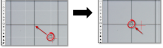
Click and drag your mouse to draw a square over a grid cell in the grid slide.
-
Then click again to complete grid creation.
-
-
A white grid with dotted lines appears in the main viewing window. Align the white grid with the slide grid (black lines).
If the slide grid appears to be lopsided compared to the white calibration grid on the screen, see Troubleshooting.
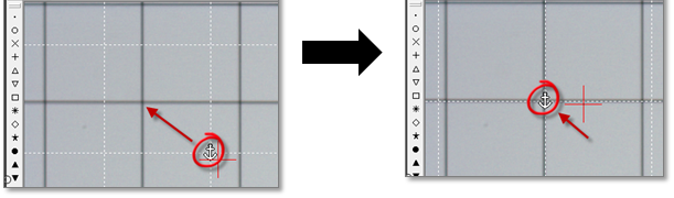
- Drag the anchor to the corner of a cell located in the top left of the screen.
- Align the vertical lines.
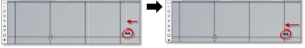
- Hover the mouse over the grid lines until the cursor changes to a double arrow.
- Drag the white dotted line to align it with the vertical slide grid line.
- Repeat until all vertical lines are aligned.
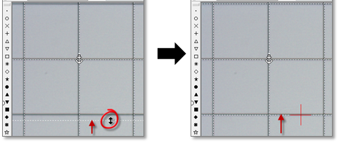
- Align the horizontal lines.
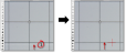
- Hover the mouse over the grid lines until the cursor changes to a double arrow.
- Drag the white dotted line to align it with the horizontal slide grid line.
- Repeat i-ii until all vertical lines are aligned.
- When the white grid is aligned with the slide grid as accurately as possible, right-click and select Finish Calibrating Current Lens
- Drag the anchor to the corner of a cell located in the top left of the screen.

Also see Calibrating your System