Reference point overview
When working with slides, placing the reference point is usually the first thing you do when creating a new data file.
Each data file contains one reference point. Tracing data is calculated and saved relative to the reference point. The reference point is essential to maintain proper alignment between slides (or images) and traces when you resume work on the same data file the next day for example.
Many functionalities are unavailable until a reference point is placed.
The reference point (or point of origin) represents the location on the physical slide or image from which all other points (i.e., all the points that constitute the objects traced) are calculated from. If the data file has multiple sections represented, this point is (0,0,0) in Cartesian coordinate space for the first section traced in the data file (if there are serial sections).
There is only one reference point per file, even if there are multiple sections and slides.
The program automatically places a reference point when you load an image or when you use a workflow.
- Start Stereo Investigator Cleared Tissue Edition.
- Drive the stage to the desired location (if you're using a microscope).
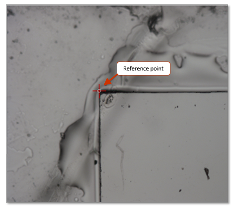
- Place the reference point by clicking in the tracing window. The reference point is represented by a small circle.
The program automatically places a reference point when you load an image or when you use a workflow.
Identify a point in the slide or in the tissue that is easy to find and recognize.
- A "+" sign on a positively charged slide
- Top left corner of the cover slip. Note that what appears as the top left corner of the cover slip on your screen may not be the actual top left corner of the slide in the slide holder.

- Anatomical landmarks:
- The longitudinal fissure on the first section of the first slide
- For NSA slides, the upper left corner of the embedding medium
- For neuron reconstruction (for which there is only one section per data file): a unique point on the section that is visually recognizable at low magnification. Make sure to add a fiducial contour easily recognizable at tracing magnification.
Joy Track is the standard joystick mode. When you leave Joy Track, your traces remained aligned with the tissue.
You can use the Joy Free mode to re-align your traces relative to the reference point. When you leave Joy Free, you can no longer move the traces.
If you forget where you placed your reference point:
- Use Joy Track to locate a landmark in your traces in the tracing window.
- Switch to Joy Free and move until the landmark is aligned with the correct location on the slide.
It would seem logical to use the same physical element (cover slip corner, anatomical landmark, or a mark on the slide) on each slide to serve as the reference point. But this may not be appropriate since that physical element may be in a different location on each slide.
Let's use an example. You have a set of three slides; on Day 1, you generate tracing data for slides 1 and 2, and on Day 2, you generate data for slide 3.
Day 1 looks like this:
- Place slide 1 on the stage.
- Place reference point on slide 1 using an anatomical landmark and trace.
- Remove slide 1 and place slide 2 on the stage; trace. The reference point that you defined for Slide 1 is applied to Slide 2; tissue and traces are aligned.
- Save and close the data file.
Then there are three possible scenarios for Day 2:
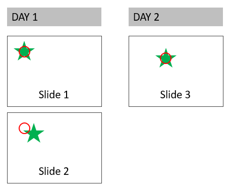
Day 2:
- Open data file created on Day 1.
- Place slide 1 on the stage.
- Place the reference point using the anatomical landmark from Day 1.
- Remove slide 1 and place slide 3 on the stage. Traces from Day 1 are lined up properly.
(NOTE: The green star represents the anatomical landmark; the red circle represents the reference point)
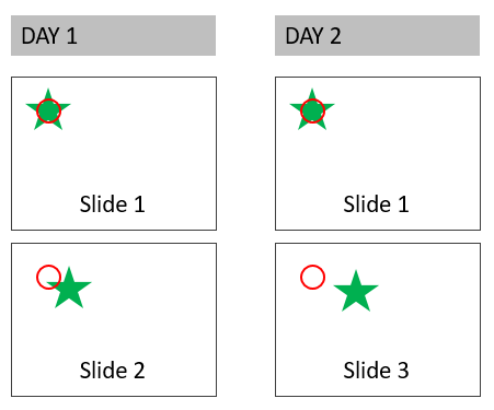
Day 2:
- Open data file created on Day 1.
- Place slide 3 on the stage.
- Place the reference point using the anatomical landmark from Day 1. The new reference point is in a different location from Day 1.
Traces associated with slides 1 and 2 are out of alignment because they were created with the reference point from Day 1 on slide 1. Using the Joy Free mode may appear to solve this problem, but it will actually disturb alignment for slides 1 and 2.
(NOTE: The green star represents the anatomical landmark; the red circle represents the reference point)
You may also consider an alternative method to avoid re-using slide 1 before each new slide.
- Place slide 1 on the stage.
- Place reference point on slide 1 using an anatomical landmark and trace.
- Change the lens to low magnification and click Move>Reference point. You should see the reference point (a circle) at the center of the screen over the anatomical landmark.
- Remove slide 1 and place slide 2 on the stage.
- Select Move>Joy Free and use the joystick to navigate the slide so that the reference point is over the anatomical landmark on slide 2.
- Select Move>Joy Free again to exit the joystick mode.
- Trace.
- Save and close the data file.
- Open the data file on Day 2 and repeat steps 5-7 for slide 3.
If you are working on a 3D reconstruction, you can follow these steps after every section instead of every slide to obtain a stack of traces. Use a tissue landmark (e.g., central canal of the spinal cord, corpus callosum) in this case.
If you have traces from previous sections that overlap with your current slide, enable Display Current Section Only in the serial section manager.
When a reference point is placed in a given focal plane, Z is set to zero in that focal plane. Generally, this isn’t an issue but there may be some exceptions. For example, let's assume that:
- On Day 1 you trace a Golgi dendrite at 100x.
- On Day 2, you carefully set the same reference point in X and Y, find the dendrite at 100x, and place spines on the dendrite.
If the Z hasn’t been carefully aligned, you may notice that the spines are too long (in Z) when you look at them in the 3D view. 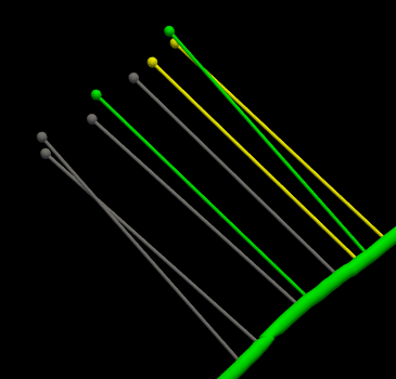 If you're only interested in spine density, this isn’t an issue, but if you're interested in spine length, your data is incorrect.
To avoid this, we recommend that you trace dendrite and spines in the same session. If this is not possible, here is what you could do to solve this issue:
- On Day 2, define the same reference point as on Day 1 to obtain correct XY alignment.
- Locate the trace of the dendrite at high magnification.
- Turn on the Orthogonal View’s Depth Filter and define its range (the smaller the range, the more accurate the alignment in Z. You can set it to 10 microns, align roughly then decrease the range and refine the alignment).

- Focus up and down until a landmark in your trace (e.g., branch) is visible (as you focus up and down, notice that your trace disappears and reappears as you are close to it; also notice that it doesn’t correspond to the tissue on the slide).
- Select the Joy Free mode.
- Notice that as you focus up and down now, your trace remains visible. Focus until the landmark in your trace is positioned at the same focal plane as your tissue, then exit the Joy Free mode.
Now, as you focus up and down, both your traces and the tissue become visible at the same time. You may turn off the Depth Filter.
