Creating a lens
For each objective in use, you need to create a corresponding software lens based on a calibration slide.
If you are using images of the MBF calibration grid slide (instead of a physical objective) to create your lenses, see Creating a New Lens from an Image of a Calibration Grid Slide.
Procedure
- Click the File>Calibration>New lens button.
- Modify the settings as needed and click OK.
- Choose a name that will lead to the unambiguous identification of each viewing mode.
- Lucivid: Direct viewing through the oculars of the microscope
- Camera or Image: Video lenses are used with a camera.
- 250 µm (the larger grid) is appropriate for low power (lower than 10X) objectives.
- 25 µm (the smaller grid) is appropriate for higher power (10X and above) objectives.
 Create New Lens settingsName
Each objective on the microscope has different calibration parameters depending on the viewing mode (video camera or Lucivid) and the magnification.
CommentsAdd comments to help you identify the lens and its conditions of use. These comments are inserted into the lens calibration file (‘stereo.len’) and do not appear elsewhere.
The comments are only displayed when editing a lens.
UnitsChange to millimeters or nanometers data tablet use or EM.
Lens CategoryZ Correction FactorYou may need to select Oil instead of Air. Or select User-Specified and enter your own correction factor in the field just under Z Correction Factor.
What is it?
The Z correction factor is used to calculate the true position of the focal plane as the microscope is moved up and down. The focal plane moves a distance that may differ from the movement of the microscope. The difference is due to the refraction of light between the cover slip and the immersion medium of the lens. Under normal circumstances the predefined values for air, oil, and water immersion lenses can be used. There are circumstances in which the predefined settings should not be used. Contact MBF Bioscience for information about unusual combinations of lenses and mounting mediums.
Calibration Box SetupBox Size
Force Square
This feature was designed for use with acquired images where a calibration square is not available and calibration must be performed with a calibration line or bar.
Under Calibration Box Setup, enter:
- 250 µm (large grid): for lower than 10x objectives
- 25 µm (small grid): for 10x and above objectives
- Create an alignment grid.
- Click and drag to draw a cell over a grid cell in the grid slide.
- Click again to display a white grid that overlays the grid from the slide.
- Align the overlay white grid with the grid from the slide.
- Drag the anchor to the top left corner of a cell from the grid slide.
- Hover the mouse over the vertical line until you see a double arrow.
- Drag the arrow until the vertical white line is aligned with a vertical line of the grid slide (for a more detailed description of this technique, see Calibrating an Existing Lens).
- Hover the mouse over the horizontal line until you see a double arrow.
- Drag the arrow until the horizontal white line is aligned with a horizontal line of the grid slide.
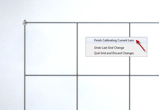
- When finished, right-click and select Finish Calibrating Current Lens.

- Repeat steps 1—4 for all your objectives.