Planar Rotator

Use Planar Rotator to estimate the volume of particles, such as cells, in isotropic and vertical sections. If you have a small population, all cells can be sampled with Planar Rotator.
Requirements
Before using this probe, you need to obtain a systematic random sample of particles; use the Image Volume Fractionator or another systematic random sampling scheme for this.
This probe requires:
- Sections cut with uniform random position in the reference space.
- Sections with either isotropic or vertical orientation.
- Sampling must be systematic within and between sections.
- A unique reference point is associated with each particle.
The first three requirements essentially ensure that estimates for particles that are not isotropic in shape, orientation or distribution will not be biased by these factors.
Using a unique reference point for each particle (for instance the nucleus of a cell) helps ensure that measurements are made at random depth along the Z-axis (measuring each cell at a depth where its largest cross-section is visible might bias the resulting volume estimates). It is usually assumed that a given number of particles will be sampled and measured. The resulting average represents the mean particle volume.
Procedure
-
 Start the Image Volume Fractionator workflow (from the Number section of the Probes ribbon) and work through the steps up to the Count objects step.
 - At the Count objects step, click the Start Counting button in the workflow and identify the first particle.
-
Click the Planar rotator button from the Volume/Area section of the Probes ribbon. Adjust the parameters as needed.
-
Select a marker in the toolbar and click an object to select it for analysis.
Use the same relative reference point for each object (e.g., nucleolus).
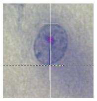
A single line is drawn through the reference point of the object.
-
Vertical sections: the line should be parallel to the vertical axis of the tissue. To change the orientation of the line, position the cursor over one of the small squares on the vertical line. The cursor changes to a hand. Drag the vertical line and align it with the vertical axis for this section.
-
Isotropic sections: align this vertical line along the major axis of the particle to be measured. This will usually help improve the variance of the estimate.
-
-
Click the line at each intersection with the boundary of the object .
The illustration (click to expand) shows the vertical line with the top intersection marked and the bottom intersection about to be marked and indicated by the dashed line.

-
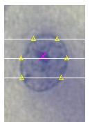
Place a tick mark by clicking the point(s) where each horizontal line intersects a boundary of the object.
This illustration shows the tick marks as yellow triangles.

-
If a line crosses multiple boundaries, place a marker at each intersection.
-
To delete a tick mark, right-click over the tick mark and select Delete?.
-
- When you have finished marking the boundaries of the current object, right-click and select Finish Current Planar Rotator.
- Click the next object to be measured and repeat steps 4-6.
- When you have finished marking all the objects of interest, right-click and select Finish Current Planar Rotator and Exit.
- To view results, use Probe Run List.