Shrinkage Correction
Section shrinkage is likely to be different along the X, Y and Z axes, particularly along the Z (depth) axis. The standard model for shrinkage assumes that shrinkage is linear. This means that the shrinkage at the top of a section is the same as the shrinkage at the bottom of a section. In fact, it implies that the shrinkage occurs equally all along any axis of the tissue.
Shrinkage correction is easy to apply when shrinkage is linear. The Z axis is multiplied by a factor to adjust the data for shrinkage. Data entered after applying Shrinkage Correction is not affected.
- To adjust the scaling of the X or Y axis, see Adjust Scaling.
Scaling Factors - Example
For simplicity, assume that a section that was cut at 80µm shrinks to a thickness of 50µm. The final tissue is 5/8 the thickness of the original tissue. To apply a correction to restore the tracing to the original size, the data must be multiplied by 8/5.
- Enter a Z shrinkage correction of 1.6 (the decimal representation of 8/5).
- Multiply 50µm by 1.6 and the result is 80µm, which is the original thickness of the material.
To apply shrinkage correction
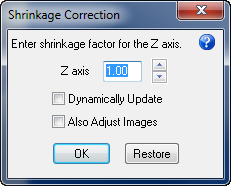
- Click Tools>Shrinkage Correction. Stereo Investigator displays the Shrinkage Correction dialog box.

- Type a value for the Z axis or use the arrow buttons to make adjustments.
- To see your changes as you make them, check Dynamically Update.
- Also Adjust Images applies the factor to images.
- Click OK to apply the changes or click Restore to return to the original values.
To apply shrinkage to a single section, select Show Current Section Only  .
.
To apply shrinkage to all of the data in the file, click Show Current Section Only again to disable it.
![]() It is important to determine how much shrinkage each section, or series of sections, has undergone during preparation.
It is important to determine how much shrinkage each section, or series of sections, has undergone during preparation.
![]() Also see Correcting for an upside-down section while tracing, Flipping a single section with a completed tracing
Also see Correcting for an upside-down section while tracing, Flipping a single section with a completed tracing
Stereo Investigator 11 | MBF Bioscience Support Center | Downloads