Contour Measurements
To view the measurements, click the Contour Measurements icon  .
.
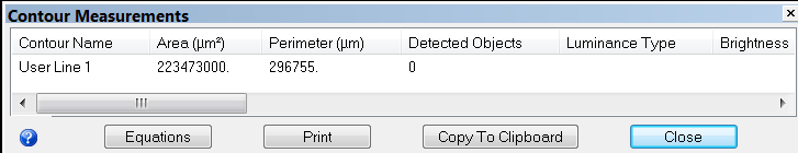
The Contour Measurements window provides an analysis of all contours visible in your current tracing. The data is updated as soon as you trace new contours.
Name that you previously defined.
- To change names, use the Options>Display Preferences>Contours tab.
Refers to the 2-dimensional cross-sectional area contained within the boundary of a closed contour.
The area is the profile area. The contour is considered to be flat when the calculations are computed, thus giving a 2-dimensional result.
The area can be displayed in square microns, square millimeters, or square centimeters.
- Use the Options>General Preferences>Numerical Formatting tab to select the desired units in which to display these results.
![]() Area is not defined for open contours.
Area is not defined for open contours.
Refers to the length of the contour for either open or closed contours.
The length takes the Z positions of the coordinates into account.
The perimeter can be displayed in square microns, square millimeters, or square centimeters.
- Use the Options>General Preferences>Numerical Formatting tab to select the desired units in which to display these results.
Perimeter is a tool that you can use to measure a two-dimensional distance that is larger than a single field of view.
To determine the distance between two points:
- Select the Contour Mapping mode. Tracing contours
- Click the first point once.
- Use the arrow movement buttons, Joy Track, or Go To to move to the second point.
- Click on the second point, and a line connects the two points.
- Right-click and select End Open Contour.
- Display the Contour Measurements window: the perimeter of the contour you just drew is the two-dimensional distance between those two points.
Another method for measuring the distance between 2 points, even across multiple fields of view, is the Quick Measure Line tool. This method does not require a contour.
Provides a summary of the total number of markers attached to a given contour.
Markers are automatically attached to a contour if they are placed while the contour is being drawn (before End Open Contour or Close Contour is selected).
If markers are drawn before the contour is started or after the contour is completed, you can attach the markers to the contour (see Attaching markers to a contour).
- Enable Collect Luminance Information to display luminance information for your closed contours in Contour Measurements.
This feature is only available on acquired images.
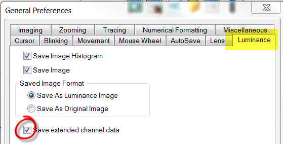
By default, this column is blank and Neurolucida uses a default method to calculate luminance data.
To view luminance data based on other methods:
- Use the Options>General Preferences>Luminance tab.
- Check Save extended channel data
 .
.
- Check Save extended channel data
- Several luminance types are displayed in the Contour Measurements window; luminance information (brightness, standard deviation, minimum luminance) varies depending on the type
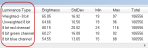 .
.
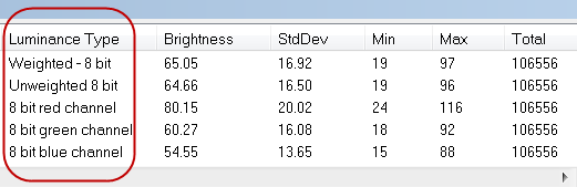
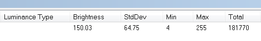
Displays the average luminance (i.e., brightness) of pixels inside a closed contour.
- Luminance ranges from 0 to 255 for each pixel.
- A black pixel has a luminance of 0 / a white pixel has a luminance of 255.
- For color pixels, the default luminance is defined as (.299*Red)+(.579*Green)+(.114*Blue).
Displays the standard deviation of the luminance of the pixels inside the contour.
Provides a numerical description of the distribution of collected luminance values.
Minimum luminance of the pixels inside the contour.
Maximum luminance of the pixels inside the contour.
Total number of pixels inside the contour at the current lens magnification.
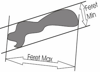
| Feret Min/Max: |
Display the largest and smallest dimensions of the contour as if a caliper was used to measure across the contour The two measurements are independent of one another and not necessarily at right angles to each other. |
|
| Aspect ratio: |
The degree of flatness of a contour shape as the ratio of its minimum diameter to its maximum diameter.
|
|
| Compactness: |
Describes the relationship between the area and the maximum diameter.
|
|
| Shape factor: |
Provides information about the complexity of a contour as defined by the relationship between the perimeter and the area.
|
|
| Form factor: |
The form factor differs from the compactness by considering the complexity of the perimeter of the object. For example, a circle with a smooth perimeter has a compactness of 1 and a form factor of 1. If the smooth perimeter is replaced with a finely jagged edge (like a cell covered in microvilli), the compactness is still near 1, but the form factor is much smaller since the perimeter is lengthened considerably.
|
|
| Roundness: |
Roundness is the square of the compactness. By squaring the value, it is easier to differentiate objects that have small compactness values.
|
|
| Convexity: |
|
|
| Solidity: |
Solidity is the area of the contour divided by the convex area. The area enclosed by a ‘rubber band’ stretched around a contour is called the convex area.
Note that it is possible to have contours with low convexity and high solidity, and vice versa. |
Use to determine an upper bound for the error of the calculation of a contour area, assuming the contour delineates the region of interest as accurately as possible at a given lens magnification.
Actual Area = Area +/- (Area Error Coefficient * Max distance from contour boundary in microns)
Actual Area is for a 1 pixel-thick contour.
Max distance from contour boundary refers to a contour that varies by no more than that distance from the boundary of the region of interest.
![]() The area error coefficient is based on the assumption that the tracing is analog to drawing the perimeter of an object with a thick pen: The thick line covers an area around the object and the true boundary of the object lies somewhere within the thick line.
The area error coefficient is based on the assumption that the tracing is analog to drawing the perimeter of an object with a thick pen: The thick line covers an area around the object and the true boundary of the object lies somewhere within the thick line.
- The outside edge of the thick line is the largest area enclosed by the contour; presumably larger than the actual area of the object.
- The inside edge encloses the smallest area enclosed by the contour; presumably smaller than the actual area of the object.
The area covered by the thick line represents the possible error in the area of the object ; this error is maximized if either the inside or outside edge traces the boundary of the object exactly.
The calculation estimates the area of the thick line (which may not be all that wide, but is at minimum one pixel in width). In general, the calculation provides a value that is larger than the actual error; that is why we refer to this value as an upper bound.
Use to determine an upper bound for the error of the calculation of a contour perimeter, assuming the contour traces the region of interest as accurately as possible at a given lens magnification.
Actual Perimeter = Perimeter +/- (Perimeter Error Coefficient * Max distance from contour boundary in microns)
Actual Perimeter is for a 1 pixel-thick contour.
Max distance from contour boundary refers to a contour that varies by no more than that distance from the boundary of the region of interest.
![]() The perimeter error is more difficult to calculate. Part of the mathematics in the derivation assumes that the contour traced is roughly parallel to the true perimeter.
The perimeter error is more difficult to calculate. Part of the mathematics in the derivation assumes that the contour traced is roughly parallel to the true perimeter.
A simple way to think about parallelism is to consider the angle between the true contour and the traced contour. An angle of 0 means that the two are parallel. An angle of 90 degrees means that the two are perpendicular. The derivation of the formula requires that the cosine of the angle is nearly 1. The cosine of 0 degrees is 1. The cosine of 10 degrees is 0.98.
The implication is that, even if the lines are 10 degrees apart, it is possible to produce a relatively good estimate of length.