Camera/stage alignment
Once you've added and tightened the objectives needed for calibrating, verify that camera and stage are aligned.
Procedure
- Verify that the camera is oriented in the proper direction: What appears through the eyepieces should be identical in orientation to what appears on the screen.
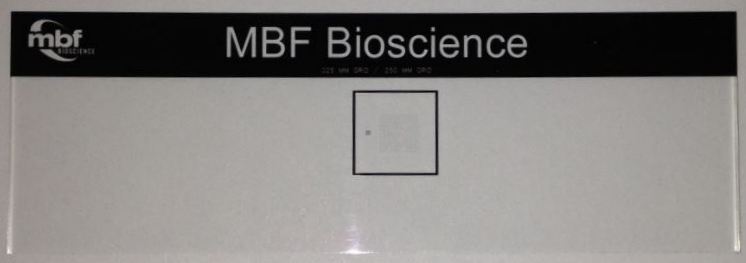
Example with the MBF calibration grid slide

If the small grid is to the left of the large grid when looking through the eyepieces, then it should appear the same way on the computer screen. If it appears backwards, you need to rotate the camera 180°.
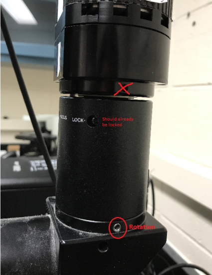
- To adjust the camera orientation, loosen the set screw and rotate the camera. Tighten the set screw when finished.
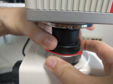
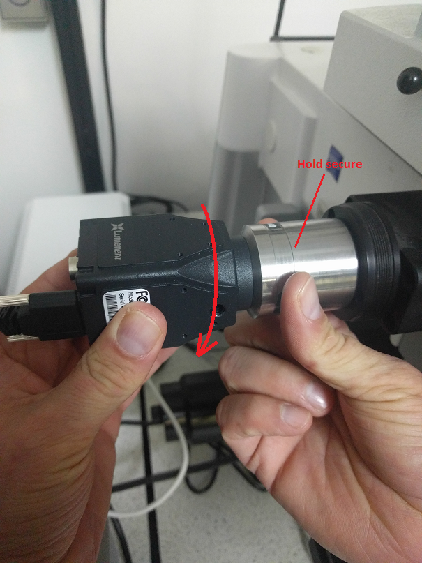
- Your camera attaches to your microscope via a part called the camera mount (c-mount). Make sure that the camera is securely attached to the c-mount: Hold your camera with one hand and the c-mount with the other, and gently rotate your camera clockwise. For all subsequent steps, you will rotate the camera and camera mount together as a single unit.

- Place a reference point on the screen (anywhere is fine).
- Click the Enable Grid button from File>Calibration; a white grid appears on the screen, displaying horizontal and vertical reference lines.
- For this step, refer to this new virtual white grid on the computer screen (instead of the black grid on the grid slide).
- To adjust the grid spacing, use File>Preferences>Display>Tracing window section. Adjust the X and Y Grid Spacing measurements as needed).
- For a preliminary alignment, at a low objective (2X or 5X), locate the large grid on the slide (250 µm) and align it closely to the grid on the screen.
Right-click and select Joy Free to control the slide movements with the joystick.
 What can I do if the two grids don't line up?
Rotate the camera and c-mount together:
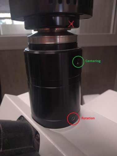
- Loosen the set screw (sometimes located at the bottom of the c-mount).
- Slowly, and only slightly, turn the camera in either direction until the two grids line up on the screen (make sure not to make large rotations with the camera or it may become oriented backwards). Camera rotation on most c-mounts can be adjusted by using a 2.5 or 3 mm hex wrench to loosen/tighten a set screw (see common c-mounts here).
- Tighten the set screw to set it into place; this provides a rough starting point for camera alignment. Aligning the grids is NOT sufficient for proper calibration.
- Continue in Joy Free mode at a higher objective (10X or 20X).
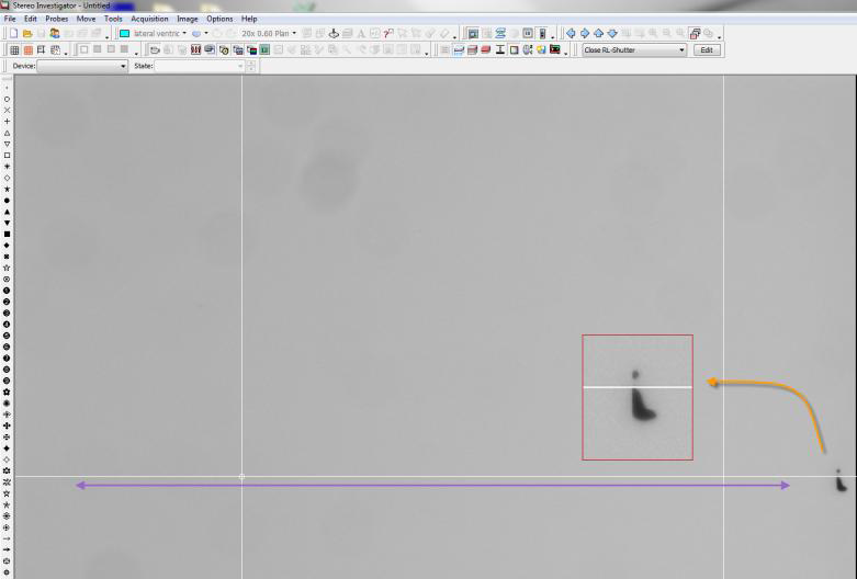
Navigate around the grid slide to find a particle easy to identify (e.g., particle with a defining mark or protrusion).
- Move the particle to the top of a white grid line on one side of the screen.
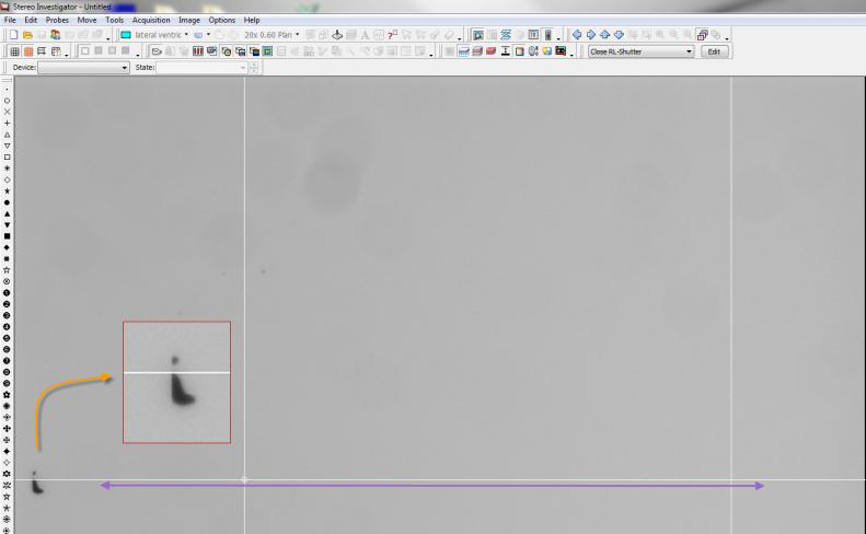
Using the joystick, move the particle across the screen to the other side on the same grid line. With a perfectly aligned camera, the particle will remain lined up with the grid line.
- If it has moved above or below the line, adjust the camera to correct for the movement: Loosen the set screw and adjust the camera before tightening the screw again.
- Continue moving the particle across the screen and adjusting for correction if needed.
Once the particle remains constant across the screen, the camera is aligned.
- Move to a higher objective and repeat steps 5–7 for a more fine-tuned alignment.


- Click the Grid icon again to turn it off.
- Once the alignment is done, tighten the c-mount securely into place. As you tighten the screws, the c-mount may move slightly. Make sure that you anticipate that movement as you align the camera.

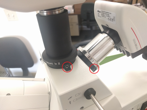
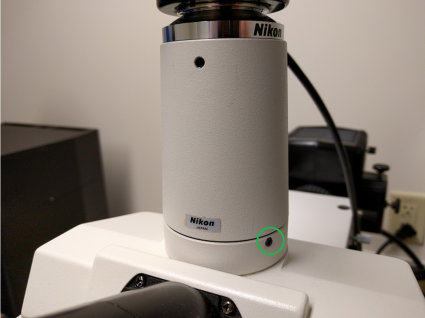
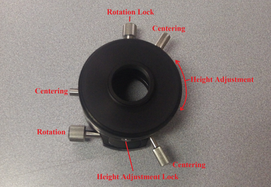
Examples of common c-mounts