Advanced settings for automatic tracing (3D)
See Trace Trees: Automatic mode (3D)
Seed detection
Sampling density: The program applies an invisible grid to sample the image uniformly at the density you specify:
- Coarse: Fewer grid lines and less sampling performed; this can result in missing branches.
- Medium: Optimizes density with speed, seed coverage, and final reconstruction accuracy.
- Dense: More grid lines and more sampling performed. Dense sampling typically leads to longer processing times to produce more seeds and increase the tracing coverage. Accuracy may not improve with this setting; it may result in seeds placed in the background where no branches exist.
Tracing
List of pre-selected values for specific image types. Use them as a starting point.
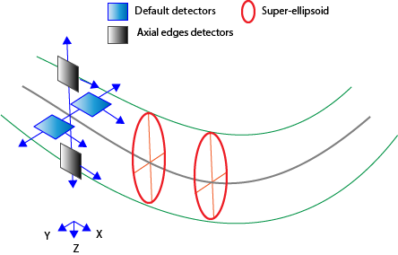
Check this box to enable detectors that are Z-aligned. These detectors are in addition to two default detectors that can move left, right, up, and down.
For best results, we recommend enabling this option for most images, but keeping it off for brightfield images.
In addition to using detectors, it is possible to fit and model super-ellipsoids at each tracing point.
- This usually gives better XYZ location and diameter estimations, and requires relatively wide processes (in pixels).
- The number of iterations affect the accuracy in fitting super-ellipsoids; more iterations will provide better accuracy; however, the analysis will typically take more time.
- [when Quick set has "Confocal: High Magnification" selected] Use the pull-down to specify that the chosen number of iterations are used "As Needed" or "Always". The "As Needed" setting may speed the analysis by allowing the software to halt when it determines that additional iterations would not enhance accuracy.
The four (top bottom left and right) detectors have a variable size (in pixels). The longer the detector, the better it responds to gaps, although it might miss curved segments.
Adjust the range to optimize the tradeoff between gap detection and curved segments detection.
The detectors move in 3D, and rotation and shifting values constrain the movement.
Maximum 3D turning angle when moving along the processes.
Movement inward or outward from the centerline when moving along. For example, if Shifting is set to 3 pixels and the right detector detects an edge 5 pixels away from the centerline, search for the next point will be implemented +/- 3 pixels away from the detected edge, i.e., between 2 and 8 pixels away from the centerline. Shifting accommodates variations in thickness along processes' length.
Branch connections
Largest gap
This value determines the largest distance that the software will "jump" to make a connection.
Max deviation angle
This is the maximum angle considered by the program when connecting branches. The maximum value is 180°.
Min ratio of diameters
When two branches are considered for connection based on their respective location in (X, Y, Z) space, the program compares the branch diameters of the end point of each branch. If the ratio of the diameters is greater than the specified value, the software connects the two branches and recolors according to the branch that
- Use the slider or type a value to set the minimum ratio.
Example:
The software compares the proximal end-point diameters of branches A and B.
- branch A diameter at end point (DA) > branch B diameter at end point (DB)
- The default ratio is 50%.
The software connects A and B if DB≥ (DA X 50%)